Introduction
In large industrial facilities a properly designed grounding system plays a vital role in ensuring personnel safety, equepment reliability, and system protection . one of the key phenomena in grounding design is Groundpotential Rise (GPR), Which occurs when fault current enters the earth and causes a dangerouse potential difference at the surface .
this article, based on international standards such as IEC 60364 and IEEE STD80, explores how the grounding network structure affects fault current paths and evaluates the resulting touch and step voltages.
System Overview and Equipment
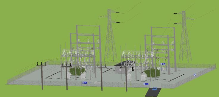
Consider a medium Voltage Substation within an industrial complex . the substation includes :
one 33 kv / 6kv power transformer
one 6kv / 400 v distribution transformer
Two 6kv – rated medium Voltage motors
Several low voltage motors
Each equipment unit (transformers and motors) has its own dedicated grounding electrod for body connection .
Both transformer are configured as Delta on the primary side and star on the secondary side
the star point (neutral ) of both transformer is grounded with the 33kv / 6kv transformers neutral grounded, with the 33kv/6kv transformers neutral grounded through a Neutral Grounding Resistor ( NGR )
the purpose of using an NGR is to limite the fault current magnitude and ensure reliable operation of protection relayse .
Fault Scenario and Possible Current Paths
Lets assume a line-to-body short-circuit occurs at the 6kv/400v transformer . one of the 6kv phases, fed from the 33kv/6kv transformer, contacts the body of the second transformer .
The short-circuit current (Isc) then flows into the ground, with two possible return paths to complete the fault loop :
Path 1 _with continuous Grounding Conductor ( Interconnected Electrodes ) :
if all grounding electrodes across the substation are interconnected via a Continuous earthing conductor, the fault current will mostly return through this low-resistance metallic path :
- Only a small portion of current flows through soil
- GPR remains very low (e.g. 10A×2Ω=20V)
- Minimal risk of dangerous step and touch Voltages
- Protection System detects the fault quickly and trips the Circuit
Path 2 _without Ground
Interconnection :
If no continuous grounding conductor is Present the entire fault Current is forced to flow through the soil and return to the source via earth :
- Full 1000A flows through
- GPR rises to a dangerous level (1000A×2Ω=2000v )
- high risk of lethal Step Voltage
- Protection System responce may be delayed or ineffective, increasing risk of injury or equipment damage
Conclusion and design Recommendations
This Analaysis Clearly highlights the critical importance of interconnecting all grounding electrodes within a medium Voltage Substation . A Well-designed grounding system :
- Minimizes GPR and associated step / touch Voltage risks.
- Ensures safe and reliable operation of protective devices .
- complies with global standards ( IEC 60364 , IEEE STD 80 )
Recommended Best Practices :